Optimizing Superheat in Twin Staged Refrigeration Cycle via Parametric Study in COCO Simulator
Table of Contents
Need for optimisation #
COCO (CAPE-OPEN to CAPE-OPEN) is a free-of-charge CAPE-OPEN compliant steady-state simulation environment which I will be using to model & assess twin stage refrigeration cycle with Propane as refrigerant.
Among many parameters that are of interest in a refrigeration cycle one is the superheat. It basically is a measure of how much extra energy (temperature macroscopically) refrigerant has attained at the outlet of chiller section (evaporator) beyond its saturation line. Now this measure is important because
- No superheat (ideally speaking) indicates that only latent heat is extracted from refrigerant in the chiller. This also means that deltaT between inlet & outlet of chiller section is zero (no sensible heat added)
- Adequate amount of superheat, however, is required to ensure no liquid phase exists at compressor inlet
- Too much superheat raises molar volume of refrigerant at chiller outlet (or at compressor suction) & thus increases work needed by compressor for a given discharge pressure
I have paid particular attention to the degree of freedom (DOF) of the system such that system Specifications & Estimates are segregated & clearly defined. Selection of these specifications is purely arbitrarily but practicing engineers should realize that this list closely resembles real process systems. For instance condenser duty isn’t but its deltaP & outletT can be easily estimated. Similarly while designing refrigeration system chiller duty already is known, this also applies to compressor where discharge pressures are known & power is to be rated.
Our system #
A twin stage refrigeration cycle (simplified without any controlled loops) as shown in the header picture is constructed in COCO like this:
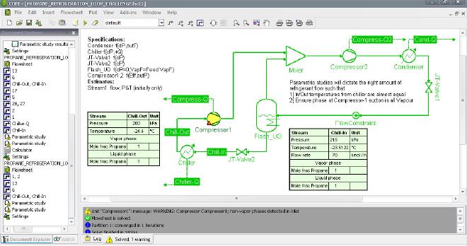
In the above picture the problem is visible indicating more than required refrigerant flow. A low quality refrigerant vapour (at chiller inlet) hasn’t all turned to gas after gaining heat at chiller. On the contrary the temperature is further reduced because there exists a deltaP across chiller as well (same deltaP that exists across JT-Valves)
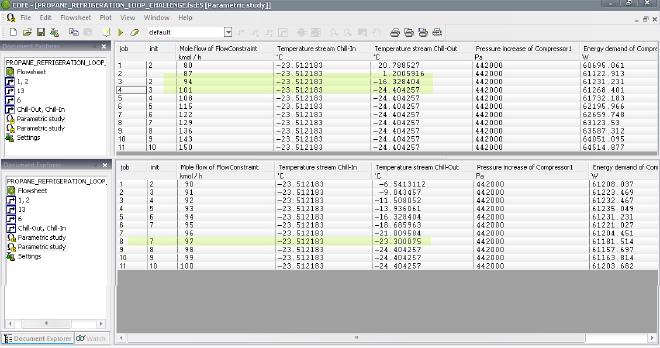
Parametric studies in COCO are highly intuitive & resembles Case Studies from which HYSYS users will be well acquainted. We define refrigerant flow as independent variable while a set of desired variables as dependent thereby producing tables like:
Initiating simulation #
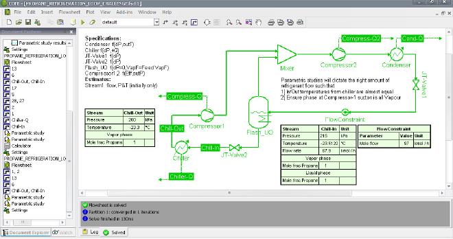
Two attempts were made to roughly judge the right amount of refrigerant that can result in zero superheat for a given JT-Valve2 deltaP. The latter will fix the inlet temperature of refrigerant to chiller because its an intensive property. Via the first table we chalk out the desired range & in the second table that range is so to speak zoomed to pinpoint refrigerant flow giving almost zero superheat. Using this as input to our case we successfully remove the initial bug:
Why superheat is important? I have given x3 points. The 1st point of zero superheat is sorted out but what about more important 2nd & 3rd points. The latter two requires some additions to our case file to make it more dynamic. Logical operators & control loops are used to make in-depth study of superheat effects like:
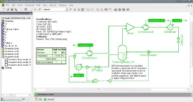
Through the above setup an additional parametric study was developed this time having two independent variables:
- Controller superheat set point
- JT-Valve2 deltaP
Depending upon your CPU the above parametric report will take some minutes to completely simulate.

Accessing simulation results #
After that we will be able to answer following questions:
- What outlet temperatures are feasible for a given deltaP across JT-Valve1?
- What outlet temperatures are feasible for a given superheat, say 5 degreeC?
- How can I simultaneously achieve say -10 degreeC outlet temperature as well as 5 degreeC superheat? To answer the 1st & 2nd question look at these plots. The blue line is the temperature after the expansion valve which is constant for a given deltaP (recall intensive property). This sets the limit for the minimum desired temperature at chiller outlet. So in a way you cannot ask for an outlet temperature of -10 degreeC when deltaP across JT-Valve1 is 200kPa. To answer 2nd question follow the black constructed lines & arrows. At given superheat & deltaP across JT-Valve1, one can acquire minimum outlet temperature at chiller. To explain it tad more verbally; you cannot have a temperature at chiller outlet less than -3.2 degreeC while maintaining 200kPa deltaP across JT-Valve1 & a superheat of 5 degreeC
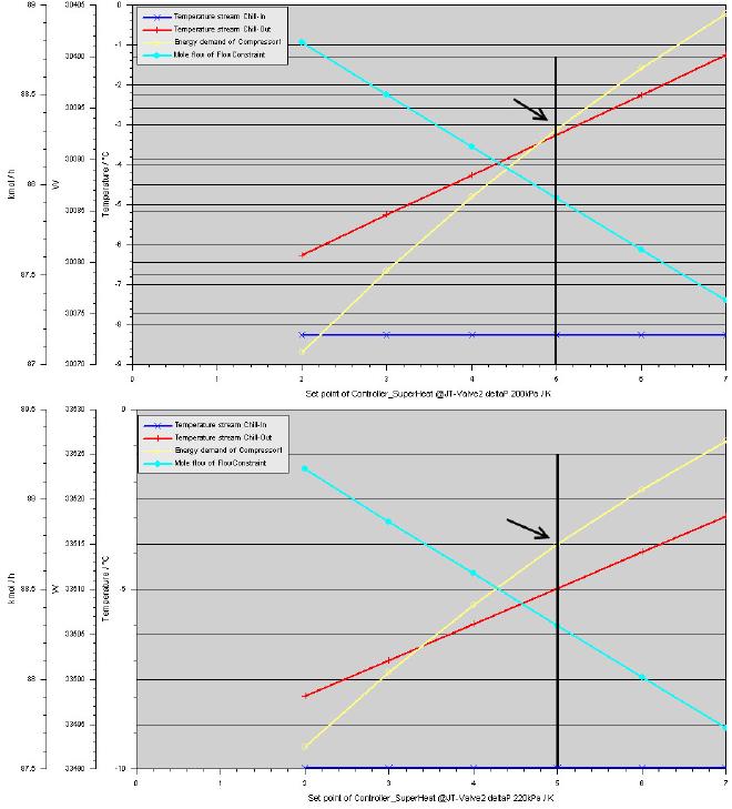
COCO allows us to plot cases in mathematically meaningful ways. The multiple y-axis feature allows us to visualize parametric relationships in a single plot alone. We will utilize this feature to answer the 3rd question. The following plot satisfies both our conditions of desired outlet temperature from chiller as well as superheat.
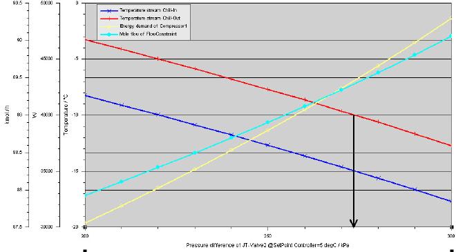
From above plots compressor power can be read & so can be the molar flow of refrigerant. All of the above pictures & case files are uploaded here. Users can modify the case file to further the investigation into parametric correlations. For instance find answers to these questions:
- Add an impurity (like Ethane) into refrigerant stream. Create a parametric study for varying impurity mole fractions & observe compressor power requirements.
- Modify the case to account for a control loop to optimize & study subcooling at condenser.