Dynamics of Critical Gas Pressure Loops in the Electrolyzer Industry
Table of Contents
This sim study is purely directed for professionals working in chlor-alkali & Hydrogen fuel-cell sector, however, if user wants to experiment with some advance dynamic features like Flow-driven system specification, Event Scheduler, Alarm Manager, Remote Setpoint …do tag along!
A brief description of this interesting process will not be a fritter of your time!
Understanding Gas Pressure Loops #
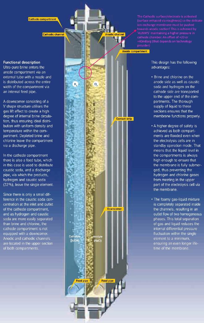
The behavior of gas pressure loops for both H2 & Cl2 are of utmost importance; where Pressure.H2 > Pressure.Cl2 by an amount of at least 5mBarg. If this isn’t ensured a mere ~3mm membrane integrity will be compromised; in a given cell this can lead to short-circuiting b/w H2 & Cl2 gases. The reaction is highly exothermic & your electrolyzer will turn into an explosive!
Here is the expression written in KaTeX syntax: $$ \Delta P = P_{\text{H2}} - P_{\text{Cl2}} \quad | \quad \Delta P \ge 5 , \text{mBarg} $$ Different technology providers have chosen an arbitrary method of maintaining this deltaP. Two different methodologies will be discussed & simulated as implemented in AKC & UHDE electrolyzers.

AKC method is cascaded where user inputs a set-point (SP) to Cl2 pressure loop & the SP of H2 pressure loop is automatically calculated via a predetermined offset addition.

UHDE method has x2 independent pressure loops. The user has two SP inputs to make for controlling each respective loop.

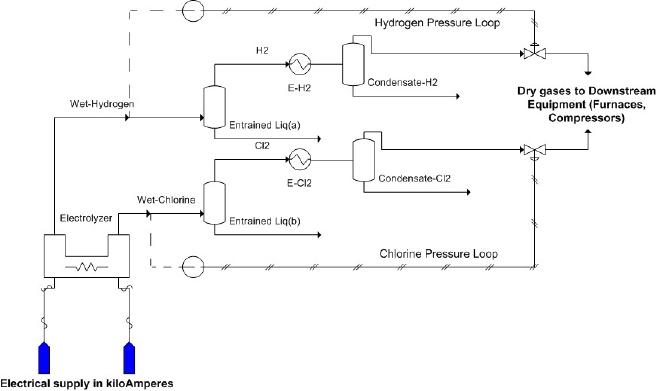
Above is a stripped down version of electrolyzer x2 gas pressure loops. Electrolyzer is a unique equipment because the products (Cl2 & H2) are produced via applying DC current of magnitude of several kiloAmperes (kA). Mass flowrates can be computed via Faraday’s law equation. In HYSYS/UNISIM this present a problem of flow-driven dynamic simulation where flowrates are solely dependent on the amount of current applied & the pressures generated are proportional to system volumes & downstream pressures. The latter is dictated by gases consumption by downstream equipment.
Simulating Pressure Loops #
The dynamics of gas pressure loops involve several key factors:
- Flow Rate: The rate at which gases are produced and removed from the system affects the pressure. Higher flow rates can lead to increased pressure if the system is not adequately vented.
- Temperature: The temperature of the electrolyte solution and the gases can influence the pressure. Higher temperatures generally lead to higher pressures.
- Valve Control: Valves play a crucial role in regulating the pressure within the loops. Proper valve control ensures that the pressure remains within safe and efficient operating ranges.
- Feedback Mechanisms: Advanced control systems use feedback mechanisms to monitor and adjust the pressure in real-time. These systems can detect deviations and make necessary adjustments to maintain optimal conditions.


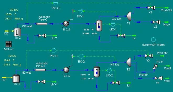
The spreadsheet unit operation (UO) indicates there are x2 Elzs each operating at 12kA with calculated production rates for each gas. For each gas flow path user can adopt piping profile, valve sizing as well as input volume for the equipment; the latter will heavily effect buffering of pressure developed henceforth. The outlet gases evolved have following conditions:
- Cl2 @ 88°C | 210-230mBarg, saturated with water
- H2 @ 88°C | 230-250mBarg, saturated with water
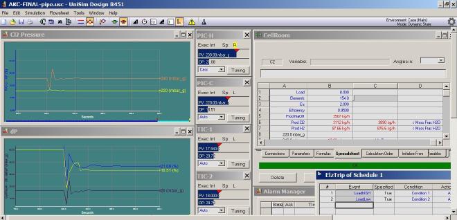
Utilizing Event Scheduler x2 process disturbances are simulated & ΔP profile (black line) is audited. Pressure controlling valves (for both Cl2 & H2) are tuned (& or detuned) to make sure ΔP remains either above 5mBarg or b/w 2-5mBarg for no more than 5sec. Alarm Manager is configured to trigger at ΔP < 5mBarg
- The 1st disturbance surrogates a sudden rectifier current jerk from 24kA → 16kA . This causes a sudden loss of flowrates & valves must close to maintain the internal pressure. The rate of valve(s) closing is critical at maintaining a +ΔP. In the stripchart labelled dp Cl2 valve opening is slightly detuned (yellow line) as compared to H2 (blue line)
- The 2nd scheduled disturbance mimics either a sudden loss of gases consumption downstream or a sudden over-consumption. The former increases downstream pressures from 140mBarg (normal) → 200mBarg. This can occur in case of a downstream tripping. An over-consumption will lead to decrement of downstream pressure from 140mBarg (normal) → 110mBarg. This can occur in case of line leak or if a superfluous egress of gases occurs somehow.
Running 2nd disturbance schedule & observing the above video; one draws real time plant conclusions:
- All is well during downstream pressure decrement from 140mBarg (normal) → 110mBarg (minimum)
- The equal percentage H2 valve is just barely able to achieve setpoint when downstream pressure approaches 200mBarg; but that is accounted for because at such pressures DCS operator will be manually venting H2 to atmosphere with the help of a parallel equal percentage H2 valve
- Lastly an unrealistic downstream pressure transition from 110mBarg (minimum) → 200mBarg (maximum) is simulated. Pressure alarms are observed & ΔP dangerously approaches towards -ive pressure values
Things to remember #
- Present temperature loops are purely fictional (you cannot directly control heat duty-Q) & thus can be replaced with real exchangers
- Changes in temperature (with changes in flowrates) in reality will not be so abrupt. One can then introduce a lag transfer function

The UNISIM sim files for both AKC & UHDE are uploaded here. HYSYS can (to my knowledge) import these files just fine, however, PM me if you need generic HYSYS case files.